In this tutorial we will create a specific layer for the AUD Pole objects, these steps can be used for all AUD objects and will allow the use of traditional AutoCAD Layer commands to control visibility.
1. Create a new layer called POLES
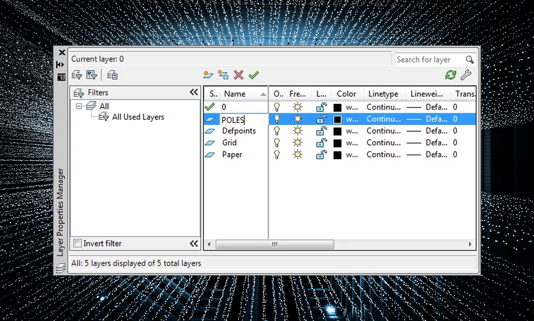
a. Type LAYER at the command line to invoke the Layer Properties Manager:
b. Click the new layer button (in red above).
c. Type POLES for the layer name:
d. Close the Layer Properties Manager.
2. In the Configuration tab in the ribbon click the Industry Model button:
3. Choose the Pole Feature Class:
4. Click on the Styles tab:

5. Click on the Default 2D Plan Symbol, then click the edit button (in red below):

6. In the Symbol Editor drop down the Layer Name pick list and choose the POLES layer:

7. Click OK to close the Symbol Editor.
8. Click Apply to save the changes in the Industry Model Configuration window.
9. Click OK to close the Industry Model Configuration window.
10. Select an existing Pole or create and a new one and view its properties (select pole, right-click, choose Properties). You will see the layer is now POLES:

11. Repeat this process for the Existing and Removal Pole Styles as well or any other AUD object type. You can create layers for each state and then can control AUD Object visibility with traditional AutoCAD layer tools.