This post is to inform how to configure the core AUD capabilities to callout and categorize material internal status (e.g. install/removal) at each work location. Several of our Customers have been using the AUD Work Location feature to filter the Bill of Material by work location. The Call Out function is then used to identify the addition and removals or features at each work location. This post will demonstrate how a user can effectively assign a work location, associate certain CUs and materials to the work location, and update both the Staking Sheet and Material List in a single action.
The first step is handled by the AUD rules. In this case the rules configuration is managed in the Expressions category, and the Text subcategory is leveraged to allow the CUs to be inserted upon creating the work location. The Material Summary expression will be used later when stylizing the block which is inserted with each work location. As seen in Figure 1, the rule states four essential criteria:
- Only materials associated with a particular work location will be considered.
- The materials will be grouped by their status (e.g. new vs. removal), and their group name will be displayed.
- The quantity of each CU will be added to the text.
- Addition of a new material or CU dictates when a new line is added to the text.

Figure 1: Rules configuration; Material Summary
expression as viewed in the AUD dialog.
The next step is accomplished using the Material List Configuration in AUD. The work location style tab (much like the Styles tab in the Industry Model Configuration) allows the user to add, edit and apply a style to each work location in the design (Fig. 2). In this case, the custom attribute I:NOTE4 references the Material Summary expression created above. Therefore, if the With Material Summary style is applied to a work location, the information referenced in the rule will be displayed.

Figure 2: Material list configuration using the user-defined expression.
After creating the Material Summary expression and assigning a work location style to reference the rule, the final step will require the user to create an additional rule (Fig. 3) in the Style category of the Rule Configuration dialog (this is very similar to assigning a style to a certain feature based on any other attribute; typically the styles are assigned to features based on the Internal Status attribute. In this case the lack of criteria for rule application implies that the text expression will appear for every work location assigned to a design).

Figure 3: Rule configuration dialog as seen in AUD.
This rule will cause any work location to display
the attributes specified by the user.
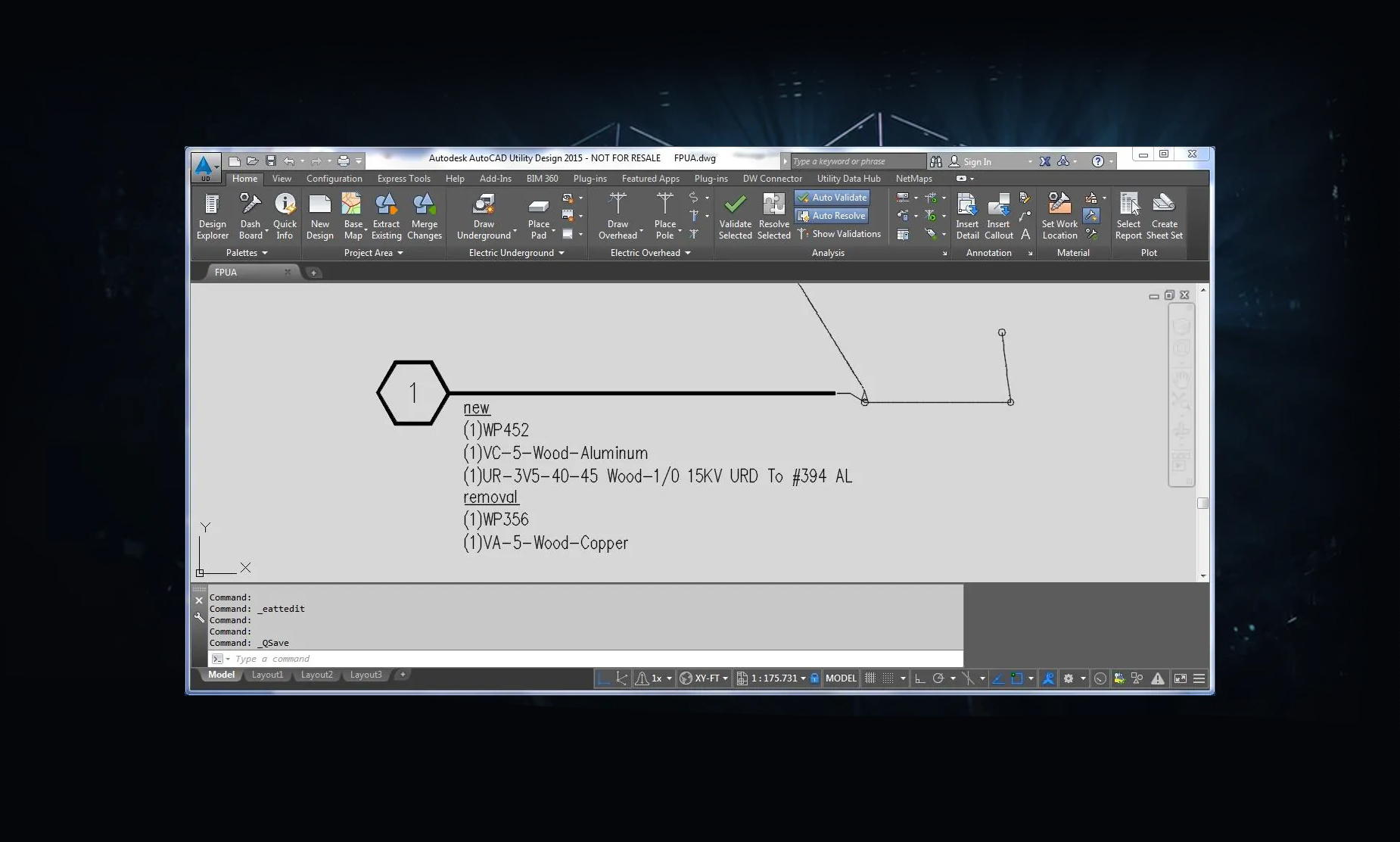
After creating the expression and style and associating the two with each other, the user can move forward by simply using the out-of-the-box functionality of AUD. The user can assign a work location, associate certain CUs and materials to the work location, and select an insertion point. Upon doing so, the desired attributes are displayed via the text expression and style applied to the work location (Fig. 4).

Figure 4: The resulting work location style.
Notice the separation of New and Removal
CUs, as well as their quantities and grop names.


Michael
September 30, 2016 9:55 amMichael,
My utility uses NISC iVUE and we are looking at options for a GIS / Staking solution. Do you know of any utilities that are currently using AUD integrated with NISC?
Thanks,
Michael